For a personal project, I decided to implement my own collision detection and resolution for 3D objects. Unsurprisingly this turned out to be quite tricky and error-prone. I used the book Real-Time Collision Detection to help out, but there were some aspects that I had to figure out myself. This is a quick post aiming to explain some of the specifics that I couldn’t find documented online.
A general collision system can be split into two parts, detection and resolution. That is, finding if a collision has taken place, and deciding what to do about it. The resolution step requires more information from the detection step than just a binary yes/no to make an informed decision.
In my project, the types of objects I am supporting are oriented boxes and triangles. I am doing simple discrete collision detection (rather than continuous detection). This means that collision detection is based on the current position of each object in the current frame. As a result, very fast-moving objects or low frame-rates will cause the system to break down. These restrictions are good enough for me, but you might find you need a much more complex solution for a different use case.
Detecting collisions with the separating axis test
The “separating axis” method for detecting collisions is outlined in a lot of detail in the Collision Detection book. I’ll give a quick explanation here.
The core idea is that for a pair of convex objects, you can be sure they’re not colliding if you can see a separation between them when looking at them in any direction.
More concretely, we can perform this test by projecting each of the shapes onto an axis (a line), and checking if there is a separation between them. They are separated if the distance between the maximum and minimum point on the axis is strictly greater than the sum of the lengths of the two projected shapes. The diagram below hopefully illustrates this.

There are infinitely many potential axes on which to project the shapes to check for separation, so we need to know which axes are sufficient to test to be sure the shapes are separated. These “potential separating axes” are different for every pair of shapes. For example, to check for separation between a pair of oriented boxes, it’s sufficient to test
- the 3 basis vectors of box 1,
- the 3 basis vectors of box 2,
- the 9 axes formed from the cross products of the bases of the two boxes.
If none of these tests find a separation, it is certain that the two boxes are overlapping/colliding.
The test is applicable any pair of convex shapes, but the axes that must be tested will depend on the shapes.
Check out the book for more details, and for the tests you need for specific shapes. Here’s an alternative source that might also help.
Resolving the collision
After determining that two shapes are overlapping, we want resolve the collision. The simplest way to resolve the collision is to push the two shapes apart so that they are no longer overlapping. If one of the shapes is movable and the other is fixed in place (for example a character and the terrain), then we want to push the movable shape the smallest possible distance that removes the overlap. If both the shapes are movable then we want to push them in opposite directions in the same axis. The amount that we move each of them could depend on some properties of the two shapes, such as mass or “friction”.
So, the information we need from the collision detection to be able to resolve the collision is the direction to move in, and the total distance needed to move. The basic separating axis test only provides a boolean result, so we need to extend it slightly to compute more information.
It turns out that from the separating axis test, we can use the axis we tested which had the smallest overlap, and its overlap distance will be the distance we need to move the objects to resolve the collision. Keeping track of the smallest overlap distance, and corresponding axis, while running the tests means we will have this information available at the end.

There are a few details to take care of. For example, we need to establish a convention for which direction our chosen axis is pointing (such as towards the first shape of the pair). We might need to flip the chosen axis to match our convention, otherwise we’ll send our shapes flying off in opposite directions in certain edge cases. Some of our tests also need special cases. For example, when one of the shapes is a triangle, we need a special case for calculating the overlap distance in the direction of the triangle’s normal (because the triangle has a thickness of zero in this direction).
We also need to think about what happens when a shape is involved in multiple collisions. Resolving one of the collisions can make another collision worse, and the order of resolution matters. In the case where I am resolving collisions with a terrain made of many triangles, I am choosing to only resolve the collision with the greatest overlap.
Implementing detection and resolution
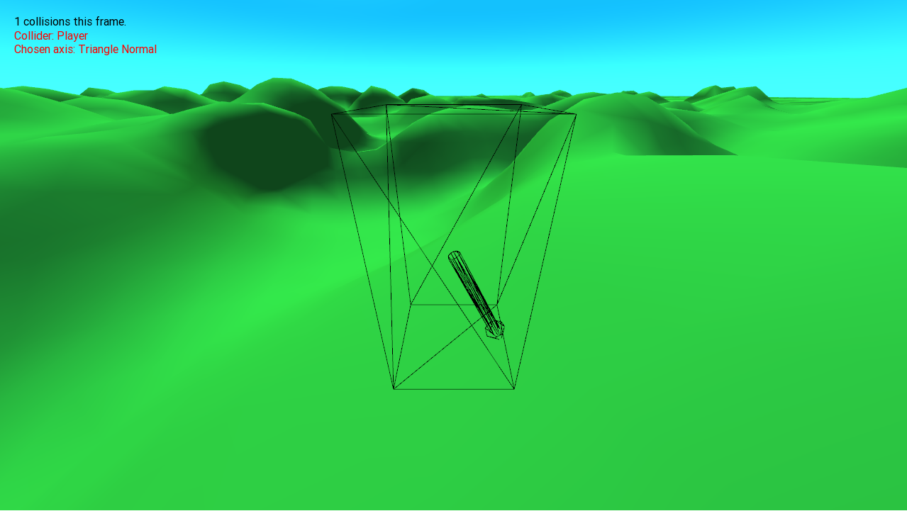
Writing these tests in code is very error-prone, and small bugs cause wildly incorrect results and are hard to track down. Using debug displays to understand what’s going on is very helpful. You can draw the axes being chosen by the tests, and log how this separating axis was created. Writing some tests can also help when you break everything by refactoring the code.
The C++ code for my project is here, and is licensed under the GNU GPL v3. The collision code is not particularly optimized, but it should give an idea of how an implementation of this might look!